Laboratory
Experiments > Loading Bridge > Technical Data
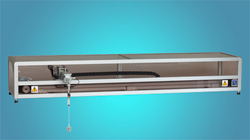
PS600
Loading Bridge
Loading
Bridge Mechanics,Motor, Sensors
By a three-phase synchronous drive, a toothed
wheel and a toothed belt a cart is driven along a guiding bar. A gear motor with a rope winch is
mounted on top of the cart. The sensors are three rotary incremental encoders for the position of the
cart, the rope angle and the rope length. The system is built on aluminium profiles and covered with a
plastic container outside of the range of the rope. The electrical signals are connected through
multi-pin plugs.
|
|
- Dimension
Sizes and
Weight of the System
- Length:
1880 mm
- Depth:
430 mm
( + 140 mm for the bridge mechanics)
- Height:
270 mm
- Weight:
40 kg
- Inputs:
- motor nominal
voltage for position control
(+24 V, nom. 12,5 A, nominal torque 0,7 Nm)
- armature
voltage for gear motor
(-24
... +24 V, nom. 2 A)
- +
15 V inductive proximity switch supply voltage
- +5
V incremental encoder supply voltage
|
- Outputs:
- position
(incremental encoder: 22,75 incr/mm, range: +⁄− 600mm)
- 2
limit switches (position left/right)
- rope
length (incremental encoder:100
incr/cm, range: 500mm)
- 2
limit switches (rope top/bottom)
- rope
angle (incremental encoder: 45,5 incr./°)
- 2
binary system identification signals
-
|
Actuator
with power supplies and system control
Inside
a 19"-case (length 470 mm x depth 370 mm x height 156 mm, weight 10 kg) there are a servo unit, a power supply
and two system control units (System Status, User Control). The system status displays whether the plant is
connected to actuator, the system is ready to operate, the plant type as well as manual/PC/ external controller.
The user control contains two keys (start manual or external controller), one potentiometer (manual control signal),
two measurement outputs (control signals for servo amplifiers) and two signal inputs (external control signals for servo amplifiers)
as well as a key to stop any controller. The panel section ‘SERVO
Bridge’ indicates the operation mode as well as the state of
the limit switches. A potentiometer allows for adjusting manually the
control signal for the servo amplifier of the rope winch motor which
is active only during pressing an accompanying key.
Actuator mains supply (220 V, 50 Hz, 400 W, on request 110 V, 60 Hz)
- Inputs ‘SERVO
MOTOR’ (Position):
- 2
limit switches (left/right)
- control
signal -10 ... +10 V
- servo
enabled/disabled
- Output ‘SERVO
MOTOR’ (Position):
- control signal for the motor
- Inputs ‘SERVO BRIDGE’ (Winch):
- 2
limit switches (top/bottom)
- control
signal -10 ... +10 V
- servo amplifier
enabled/disabled
- Output ‘SERVO
BRIDGE’ (Winch):
- armature
voltage for the gear motor
Extension
kit loading bridge(Option 60-30)
Premounted
plate with bearings, two rotary encoders, electrical connections
and gear motor with rope winch (rope length 50 cm, weight of load
210 g).
Technical
data are subject to change (Date 9-March-2024) |