
SC30 Speed Control
with Variable Load
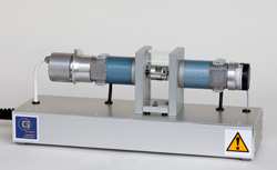
The laboratory experimental setup "Speed Control with Variable Load SC30" contains the technical realization of a nonlinear single-input/single-output system with appropriate actuator, sensors, measurement outputs and the possibility to connect different controllers. |
 |
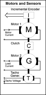 |
The plant is represented by a permanently exited DC-motor (M1) of
which the input signal (armature current) is provided by a current
control loop. Its servo amplifier allows the 4-quadrant mode. The free end of the motor shaft is fixedly
coupled (C) to the shaft of a second, identical motor (M2). This motor
is used as a generator. Its output current is freely adjustable. The
sensors for the output signal (speed) are a tacho generator (T) which is coupled to the generator and
an incremental encoder (I) coupled to the motor. |
|
The standard version of the laboratory experiment SC30 also includes an analog PI-controller which is integrated in the actuator. The speed setpoint of the motor and the load current of the generator are adjustable by providing DC voltage in the range +/-10 Volt to BNC jackets. The measurement signal for the controller is provided by the tacho generator. The proportional and integral portion of the controller can be adjusted by coefficient potentiometers. For the simulation of failures the actuator also provides an electrical disturbance unit. The corresponding panel section of the actuator contains switches and potentiometers to simulate failures. The manipulated signals are the tacho generator signal and the control signal for the servo amplifier of the motor. Both signals can be scaled or switched off.
|