Laboratory
Experiments > Speed Control > Technical Data
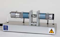
SC30 Speed Control
with Variable Load
Mechanics, Motors, Sensors
Two identical DC-motors are mounted on a platform built of aluminium
profiles. The drive shafts of the motors are coupled rigid. One
motor is used as the drive for the speed control system. The other
motor, the generator, is used as variable load. The sensors are
a tacho generator and an incremental rotary encoder for the speed.
The electrical signals are connected through a multi-pin plug.
|
|
|
Mechanical
Data:
- Length
: 480 mm
- Depth
: 150 mm
- Height
: 160 mm
- Weight
: 5 kg
Technical
Data for both motors:
- Nominal
voltage : 24 V
- Nominal
current : 2 A
- Nominal
power : 30 W
- Nominal
speed : 3000 rpm
- Nominal
torque : 0.096 Nm
|
Tacho
generator:
- Analog
voltage : 5 V / 1000 rpm
Rotary encoder:
- Power
supply : 5 V, max. 150 mA
- Line
count : 1024
- 2
TTL square-wave signals with index signal
|
Actuator
with signal adaption unit
Inside
a 19"-case (length 471 mm x depth 340 mm x height 152 mm, weight
8,7 kg) there are two 4Q-current controllers (servo amplifiers), a signal
adaption unit, measurement outputs, power supplies, an analog controller and an electrical disturbance unit.
|
Mains:
Inputs
servo amplifiers
- Supply
voltages: ± 35 V, 50 W
- Control
signal: ± 10 V (0.23 A/V)
Inputs
signal adaption unit:
- 2
control signals, range: ± 10 V (*)
- Servo
amplifier enabled/disabled
- Speed:
5 V/1000 rpm, V=0.5
- Monitor
of motor current: 0.2 V/A, V=22.0
- Monitor
of generator current
0.2 V/A, V=22.0
|
Outputs
servo amplifiers:
- Armature
current for the motor/generator: max. ± 2.0 A (± 8.0 A, 10 ms)
- Current
monitor: 0.2 V/A
Outputs
signal adaption unit:
- 2
control signals, range: ± 10 V
- Speed:
2.5 V/1000 rpm, max. ± 10 V (*)
- Motor
current 2.0 V/A, max. ± 10 V (*)
- Generator
current 4.4 V/A, max. ± 10 V (*)
(*)
= Measurement output at the front
|
Analog
Controller
Analog
PI-control of the speed. Extern control voltage for setpoint of the speed
and the amount of the
load via BNC sockets. Switches for the release of the servos.
Inputs
:
- Tacho
signal from the signal adaption unit:2.5 V/1000 rpm
- Setpoint
for speed: ± 2.5 V/1000 rpm, max.± 10 V
- Setpoint
for the load current: ± 0.215 A/V,max. ± 10 V
Output:
- Control
signal for the motor servo: ± 10 V
|
Electrical Disturbance Module
The tacho signal and the control signal
for the servo can be switched off manually and scaled by adjusting potentiometers.
|
|
Technical
data are subject to change (Date 9-March-2024) |