Laboratory
Experiments > Ball and Beam > Technical Data
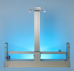
BB50
Ball and Beam
Ball
and Beam, Motor, Sensors
By
a DC-motor, a toothed wheel and a toothed belt a beam is driven
around its centre point. Changing the angle of the beam will change
the position of a ball rolling upon the beam. The sensors are one
rotary incremental encoder for the beam angle and one CCD camera
to measure the ball position. Two lamps can be switched on to support
the camera. The system is built on aluminium profiles and covered
with transparent plexiglass mounted on the front and rear side of
the system. The electrical signals are connected through a multi-pin
plug. |
|
- Dimension
Sizes and
Weight of the System:
- Length:
1105 mm
- Depth:
215 mm
- Height:
1025 mm
- Weight:
18 kg
- Output:
- 2
limit switches (max. angle left/right)
- angle
(incremental encoder: 0.018°/incr)
- position
(video signal from CCD camera)
|
- Inputs:
- armature
voltage (24 V, nom. 2 A,
nominal torque 9,6 Ncm)
- +24
V lighting supply voltage
- +15
V limit switch supply voltage
- +5
V incremental encoder supply voltage
|
Actuator
A
19"-case (length 471 mm x depth 340 mm x height 152 mm, weight
11 kg) contains a servo amplifier, two power supplies, a sensor module
and a user control unit. The servo amplifier operates on the DC motor
driven by an analog control signal. The power supplies provide the
neccessary voltages for all actuator units. The corresponding front
panel sections indicate the availability of the voltages, the system status
(plant is connected to actuator, system is ready to operate) the
controller type (manual, PC, extern). One of the panel sections contains a
key to stop any controller. The monitor unit provides an analog signal
and binary signals (11 bit parallel) according to the video signal.
Its front panel section contains measurement outputs for the ball position,
the beam angle and the control signal. The user control section provides
the control and enable signal for the servo amplifier. Its front panel section
contains two keys ( start manual or external controller), one potentiometer
(manual control signal), one signal input (external control signal
for servo amplifier) and a switch for the lighting.
Actuator
mains supply (220 V, 50 Hz, 140 W, on request 110 V, 60 Hz).
- Inputs
servo amplifier:
- control
signal -10 ... +10 V
- servo
amplifier enabled/disabled
- Output
servo amplifier:
- armature
voltage for the motor
- Outputs
monitor unit:
- ball
position -10 V ... +10 V
- beam
angle channel A (TTL)
- beam
angle channel B (TTL)
- control
signal -10 ... +10 V
Technical
data are subject to change (Date 9-March-2024)
|