Laboratory
Experiments > Position Control > Technical Data
PC60
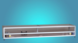
Position Control
Position
control plant, Motor,Sensors
By a three-phase synchronous drive, a toothed
wheel and a toothed belt a cart is driven along a
guiding bar. One sensor, a rotary incremental
encoder, measures the position of the cart. The
system is built on aluminium profiles and covered
with a plastic container outside. The electrical
signals are connected through multi-pin plugs. |
|
- Dimension Sizes and
Weight of the System:
- Length: 1880 mm
- Depth: 430 mm
- Height: 270 mm
- Weight: 40 kg
Inputs:
- motor nominal voltage (+24 V, nom. 12,5 A, nominal torque 0,7 Nm)
- + 15 V inductive proximity
switch supply voltage
- +5 V incremental encoder
supply voltage
-
|
- Outputs:
- 2 limit switches (left/right)
- position (incremental
encoder: 0.044 mm/incr, range: +⁄− 600mm)
- 2 binary system identification
signal
|
Actuator with power supply and
system control
Inside
a 19"-case (length
470 mm x depth 370 mm x height 156 mm, weight 10 kg) there are a servo
unit, a power supply and two system control units (System Status,
User Control). The system status displays whether the plant is connected
to actuator, the system is ready to operate, the plant type as well
as manual/ PC/ external controller.
The user control contains two keys (start manual or external controller),
one potentiometer (manual control signal), two measurement outputs (control
signals for servo amplifiers) and two signal inputs (external control
signals for servo amplifiers) as well as a key to stop any controller.
The servo amplifier for the system Loading Bridge is already included in the standard version.
Actuator mains supply (230 V, 50 Hz, 400 W, on request 110 V, 60 Hz)
- Inputs servo unit:
- 2 limit switches (left/right)
- control signal -10
... +10 V
- servo amplifier enabled/disabled
- Output servo unit:
- control signal for
the motor
Technical
data are subject to change (Date 9-March-2024)
|