Laboratory
Experiments > Tank System > Technical data
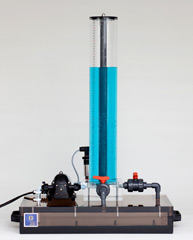
TS21 Tank-System
The tank system consits of a cylindrical tank and
a pump which are mounted on top of a rectangular
container. The pump driven by a DC motor sucks
distilled water out of the container and supplies the
cylindrical tank. On its base there is a manual valve
as nominal outflow allowing the liquid to flow
continuously back into the container. This closes
the cycle. Using a second manual valve an
additional opening in the cylindrical tank can be
opened. The level of the liquid is measured by a
process pressure transmitter.
The container and the cylindrical tank build one
unit and are made of plexiglass.
The model and the accompanying actuator are
connected by a 6-polar plug.
|
|
Physical dimensions and weight of the system:
- Width : 565 mm
- Height
: 815 mm
- Depth
: 360 mm
- Weight
: 19 kg
|
Pumps:
- Type
: Diaphragm pump
- Supply voltage
: 12 V
- Input current : 1.4 A
- Maximum flow: : 7 l/min
- Pressure
: 1.4 bar
|
Sensor:
- Range
: 0 ... 100 mbar
- Output
signal : 0 ... 20 mA (two-wire)
|
|
Actuator
with signal adaption unit
and analog controller
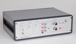
Located inside a 19" housing are the power
supply, the servo amplifier for the pump, the signal
adaption unit and the analog controller. An
external controller can be connected alternatively
either via USB interface or 37pol. DSUB
connection.
Mains: (220 V, 50/60 Hz on request 110 V, 60 Hz)
Inputs servo amplifier:
- Control signal for the pump: 0..10 V
Output servo amplifier:
- Output voltage for the pump: +12 V (PWM)
Inputs
signal adaption unit :
- 3
sensor signals, range: 0 ... 20 mA
- 2
control signals for the pumps in the range: -10 ... +10 V
Outputs
of the signal adaption unit :
- Liquid level of the cylinder: +10..-10 V for
external controller
- Control signal
for the pump: 0..10 V
Analog controller:
Two setpoints for the height are adjustable by
potentiometers. Switching from one setpoint to the
other produces step responses. Proportional and
integral portion are adjustable by a ten turn
potentiometer with precision knob. The integral
portion can be switched off. The controller can be
linearized about the operating point by using a feed
forward signal for the servo amplifier. The feed
forward signal can be adjusted by a potentiometer.
All operating elements (switches and potentiometers)
and the sockets for the measurement
outputs are placed on the front panel together with
a clearly visible block diagram.
Measurement outputs on the front panel:
- Setpoint 1 for the height: 0..6 V
- Setpoint 2 for the height: 0..6 V
- Actual height: 0..6 V
- Feed forward signal: 0..10 V
- Control signal for servo: 0..10 V
External digital controller
As external controller a PC with USB interface
or PC with an A/D-D/A plug-in card
can be used.
Inputs
:
- Sensor signals: -10...+10 V to 12
bit A/D converter
for USB
Outputs
:
- Control signals for pump servo: -10...+10 V from12 bit D/A conv.
for USB
Technical
data are subject to change (Date 9-March-2024) |