
Adapter Box V2 for
|
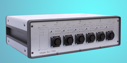 |
The task of the Adapter Box with converter electronics is to convert a digital TTL-signal to the power signal (24VDC/1A) for the motor of the control valve, to generate a digital signal for the right and the left limit of the valve and to map the potentiometer output to a voltage range of -10V...+10V. The Adapter Box consists of a 19ď housing with 2 power supplies (24VAC/6A and +/-15VDC, +5VDC) as well as 6 independant converter electronics. When using the Adapter Box V2, the Three-Tank-System is connected to the Adapter Box with a 37pol. DSUB cable. The connection to the PC-adapter cards is provided by two 37-polar DSUB connectors on the rear panel of the Adapter Box. An electrical control valve can easily be connected with its special cable to the corresponding socket on the front panel of the Adapter Box. One switch is located on each panel section of the converter electronics for the operation mode with PC (automatic) and manual mode (open/close). 4 LEDs indicate that the valve is completely closed/opened and the direction of rotation of the motor (right/left). Order Codes
As accessory for the laboratory experiment ďTTS20
Three-Tank-SystemĒ: Technical data are subject to change (Date 9-March-2024) |